Interactive 3D requires WebGL. The source process video remains available above.
Measure every socket centre from the First End cut face. Distances are absolute: for example, socket #1 at 500 mm and socket #2 at 4,000 mm.
Socket #1 sets the clock reference. For later sockets, leave the angle blank for the same orientation, or enter an offset such as 45°. Looking from First End: 0° up; positive angles turn clockwise. Sockets are radial to the pipe.
Close this editor, then Run this batch. Cutting happens underneath; the pipe rotates to present the opening upward for welding.
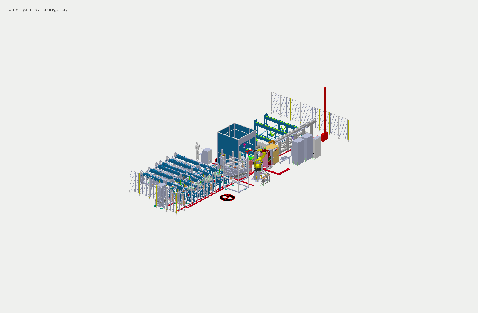
The machine geometry comes from your supplied Q64 TTL Pipe Robotic Welding Line.STEP. The original assembly can be viewed with Original CAD pose.
Updated 10 September 2026: underside cutting, coordinated robot access and indexed outgoing movement follow your latest process instructions. Travel, joint motion and cycle times are demonstration settings; STEP does not contain the robot controller program.
Sample pipe dimensions demonstrate the sequence. They do not establish the machine’s approved capacity.
 AETEC© 2026 Aetec Pte Ltd